SUMMARY:
This project is about a simple obstacle avoiding robot using INTEL EDISON.Robotics is an exciting and fun hobby that has become very affordable in recent years.Lets do it.
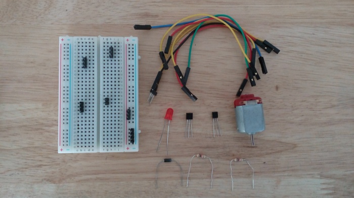
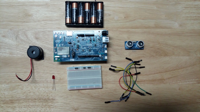
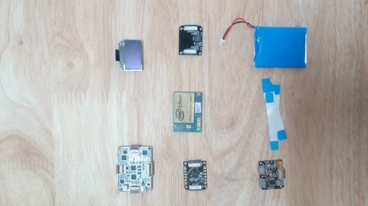
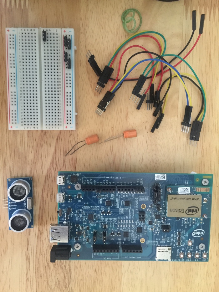
PARTS LIST:
- Cardboard.
- Battery.
- Ball bearing for front roller.
- 2 servo motors.
- 2 matching wheels.
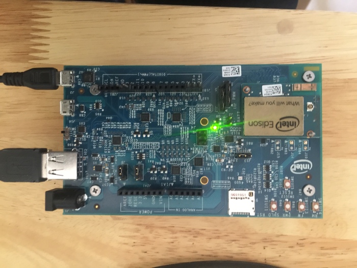
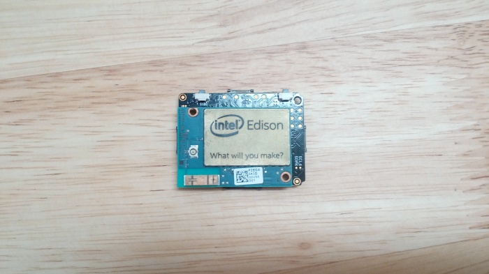
- Intel Edison with Arduino breakout board.
- Breadboard.
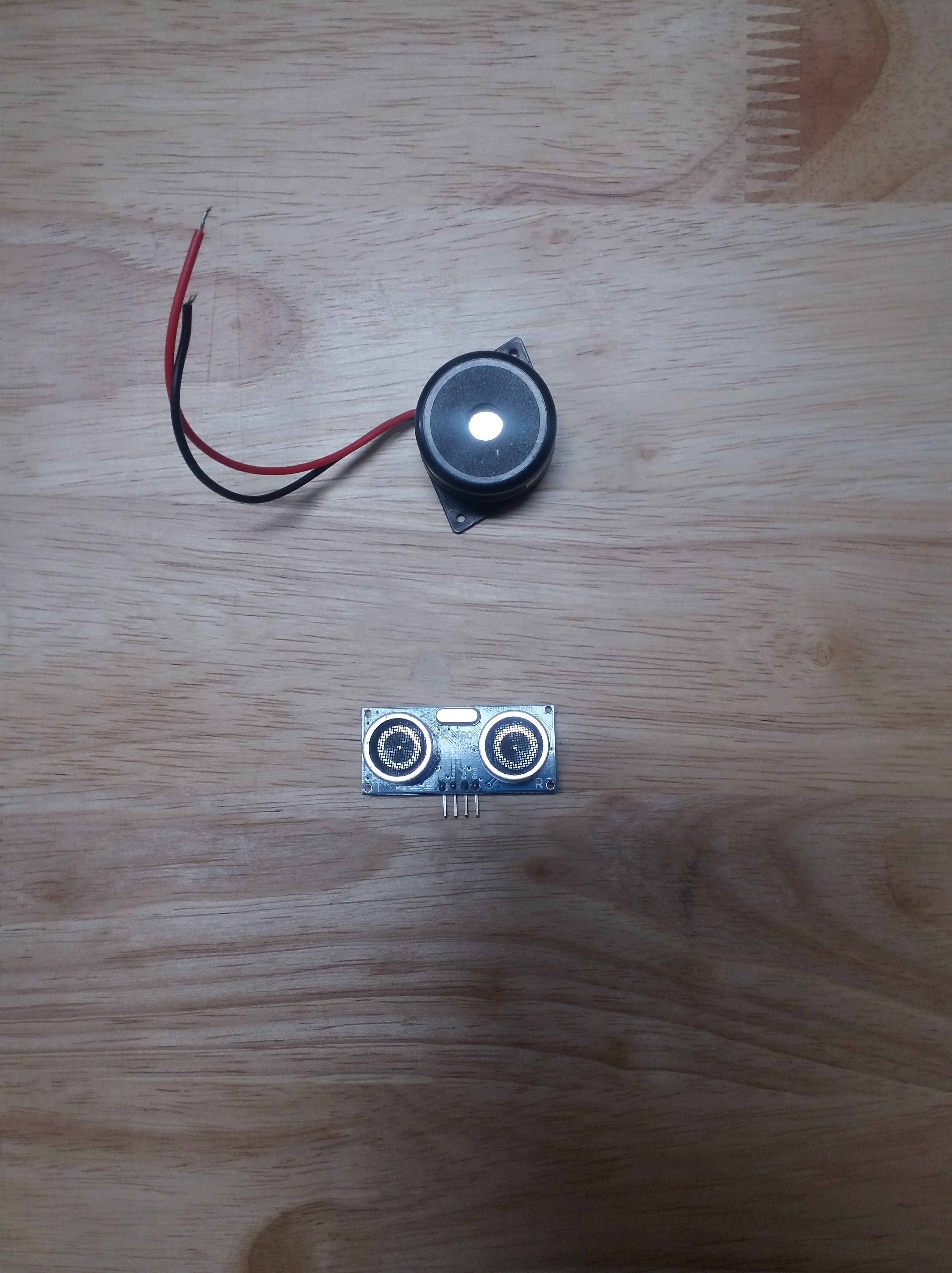
- Ultrasonic Range sensor – HC-SR04.
- Capacitors (220uF).
- Jumper Wires,rubber bands,Glues, etc…
STEPS TO BE FOLLOWED:
STEP 1: CHASSIS.
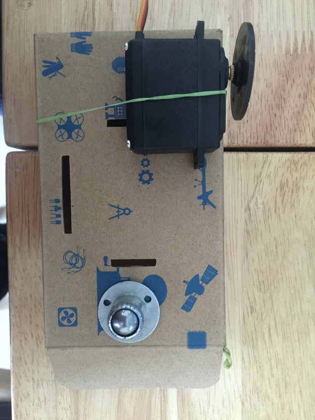
We chose a simple cardboard based chassis with the servos attached to it with the help of rubber bands. Make it convenient for your use.
The above choices work as long as your rover is roving over smooth surfaces. Attach the front ball bearing in front of the cardboard.
Set front wheel ball bearing: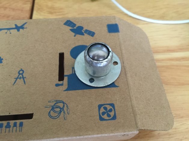
Attach single servo motor:
Attach both servo motors:
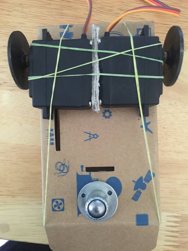
our chassis is ready.
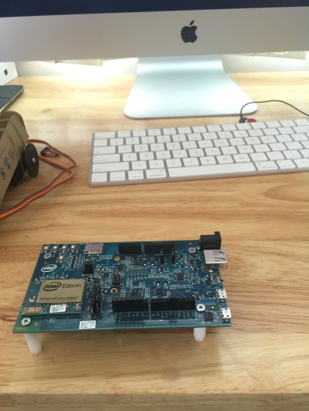
STEP 2: ARDUINO BOARD WITH INTEL EDISON.
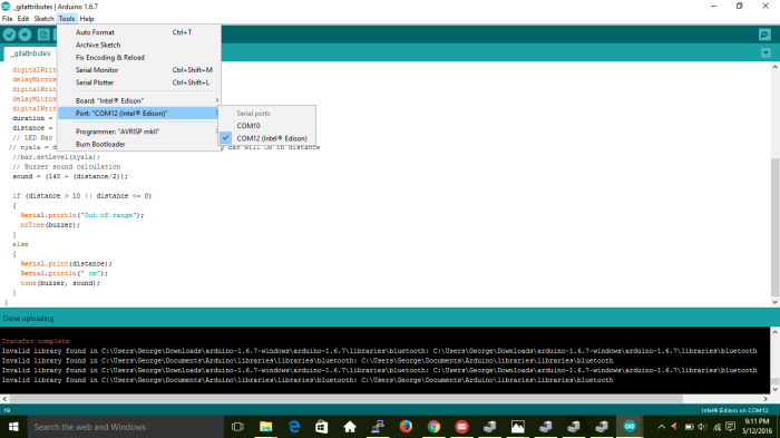
Configure your arduino board with intel edison.Look at this link to configure ( https://software.intel.com/en-us/iot/library/edison-getting-started).
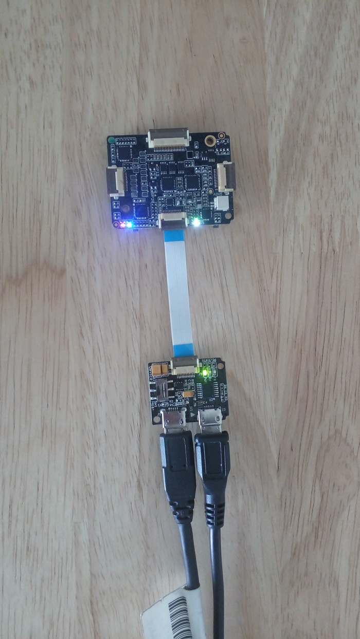
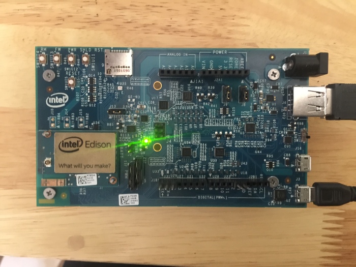
Make sure your serial communiction and port are fixed. Check out your arduino board with intel edison by loading a simple program to your board.
Lets check out our board with simple blinking led.
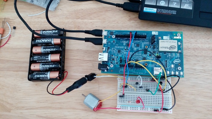
STEP 3: BATTERY AND BOARD.
Mount this battery using battery holder and board then later secure it to the chassis using rubber bands – surprisingly this works pretty well
(remember this is planned on using this on smooth surfaces only – adjust the attach according to your plans).
We have to use 6 AA battery holder in order to hold six batteries (based on motors you can use your batteries).
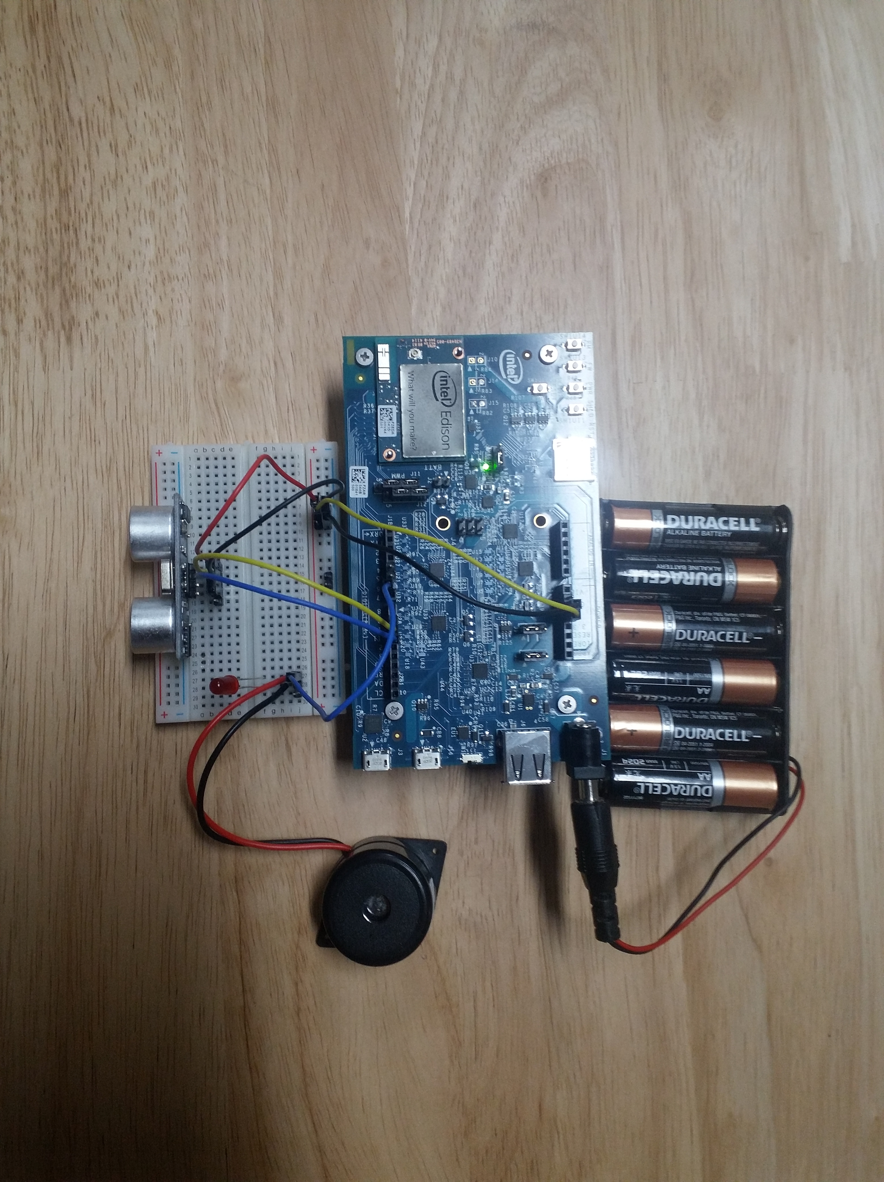
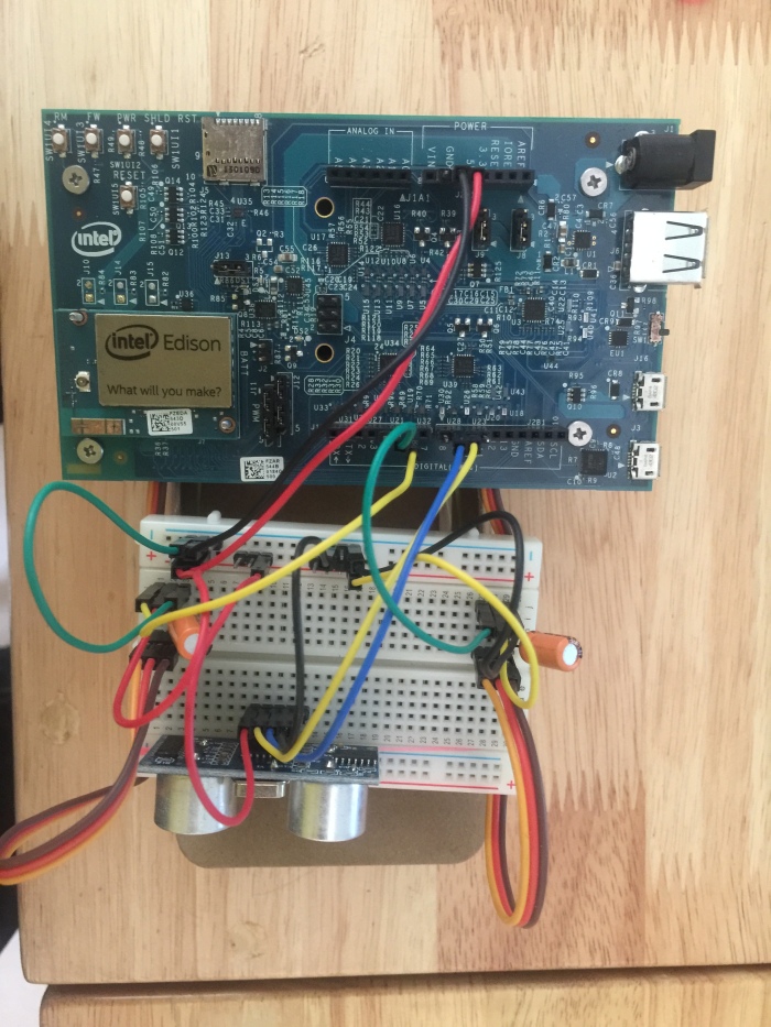
STEP 4: ARDUINO PINS.
These are the ARDUINO PINS which it is attached for this project.
You can set the pins on your own.
Ultrasonic Range Sensor (HC-SR04) ECHO 9
Ultrasonic Range Sensor (HC-SR04) TRIG 10
Servo signal (left) 5
Servo signal (right) 6
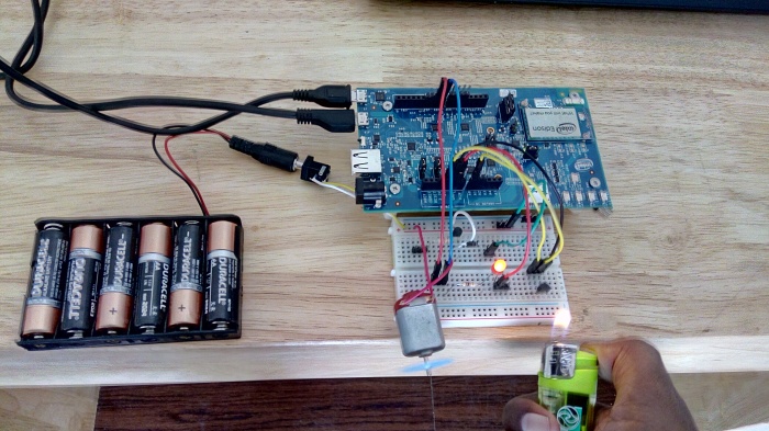
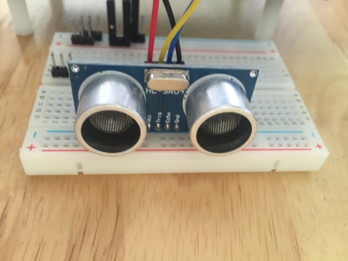
STEP 5: ULTRASONIC RANGE SENSOR (HC-SR04).
First of all check Ultrasonic Range Sensor (HC-SR04) by using a simple arduino code.
Connect the ultra sonic sensor using some jumper wires.
Here we have checked our ultra sonic sensor using simple program.
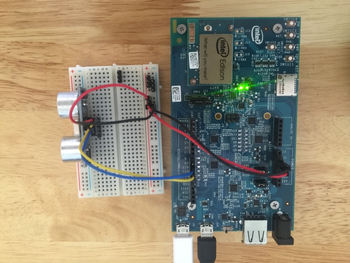
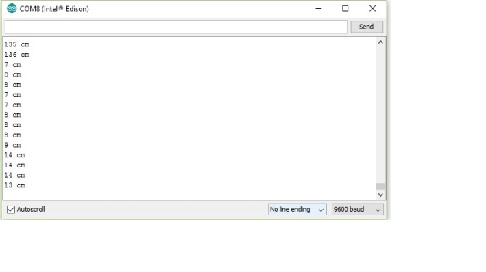
By checking in serial port of arduino uno we can have a clear thought that it is working . Ultrasonic sensor shows the distance of the object in front of it. Here in our code distance is calculated in centimeter.
Below image shows the distance calculated by ultrasonic sensor in serial port (cm).
STEP 6: SERVO MOTOR CONNECTIONS
The wiring needed for connecting the servo cable — 3 pin connection coming out from the servo – red (vcc), black(ground) and in my case yellow(signal).
The picture (Servo wiring 1) shows the 220uF capacitor connected between vcc/ground – this is needed for each servo in order to avoid the brownout issues.
Since we are using the same battery source to power the servos and the board.
on sudden rover turn of directions, there can be spikes of current draw which can cause the board to recycle if we don’t provide a sizeable capacitor (220uF works just fine in our case).
The pictures show wiring for 1 servo without the servo cable attached (Servo wiring 1) with the servo cable attached (Servo wiring 2) and then both the servo cables attached.
STEP 7: CODING AND TESTING
Apply the code and test it.
#include<Servo.h>
#define trigpin 10 // Trigger pin
#define echopin 9 // echo pin
Servo servoLeft;
Servo servoRight;
int forward = 180;
int backward = 0;
void setup() {
Serial.begin(9600);
servoLeft.attach(5);
servoRight.attach(6);
pinMode(trigpin, OUTPUT);
pinMode(echopin, INPUT);
}
void loop ()
{
int duration, distance;
servoRight.write(forward);
servoLeft.write(forward);
digitalWrite(trigpin, HIGH);
delayMicroseconds(1000);
digitalWrite(trigpin, LOW);
duration = pulseIn(echopin, HIGH);
distance = ( duration / 2) / 29.1;
delay(1000);
if (distance >= 10)
{
Serial.print(distance);
Serial.println(” cm”);
}
else
{
Serial.println(“danger”);
servoLeft.write(90);
servoRight.write(90);
delay(1000);
servoLeft.write(backward);
servoRight.write(forward);
delay(5000);
servoLeft.write(forward);
servoRight.write(forward);
}
}
Now we have done.
Here is our simple obstacle avoiding robot using intel edison.
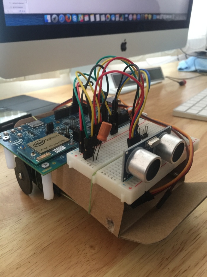
This is about simple moving Robot using intel edison.